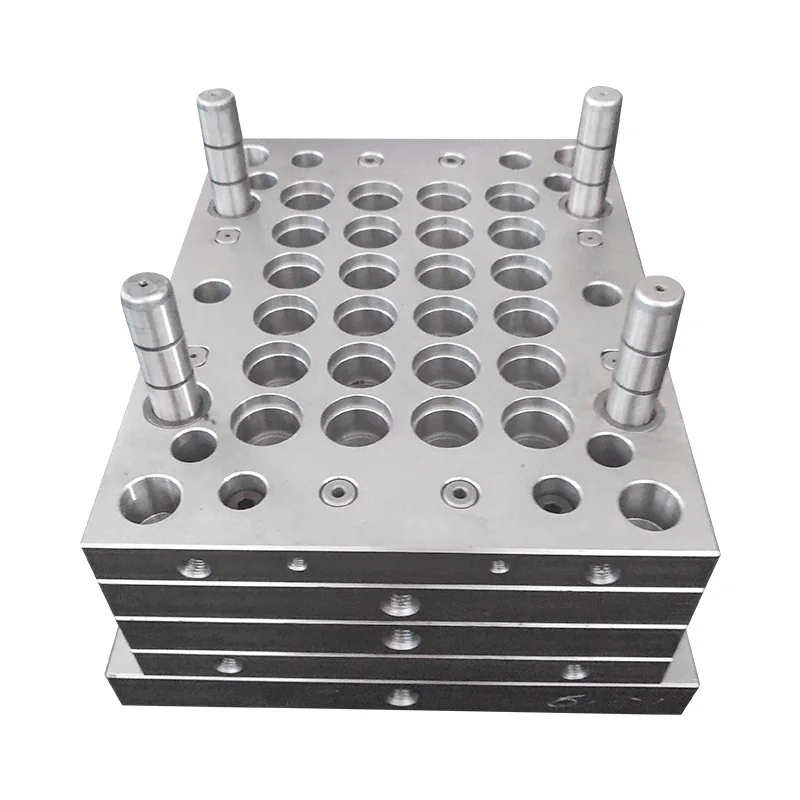
Machining and Guide-Assembly Options
Each catalog reference carries its selected scope into the quotation form. Finished dimensions, material records and acceptance follow the approved order.
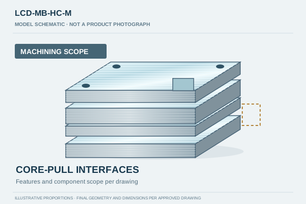
Machining scope
Drawing-specific plate and feature machining. The quotation identifies supplied parts and inspection; assembly is separately defined.
- Supply scope
- Plate/feature machining
- Interface review
- Cylinder mounting interfaces; core movement and clearances; plate strength features; included components. Hydraulic cylinders are not automatically included.
- Overall capacity
- Footprint up to 1500×1200 mm; approximately 8 tonnes per set maximum, subject to drawing review
Cylinder mounting interfaces; core movement and clearances; plate strength features; included components. Hydraulic cylinders are not automatically included.
Request this option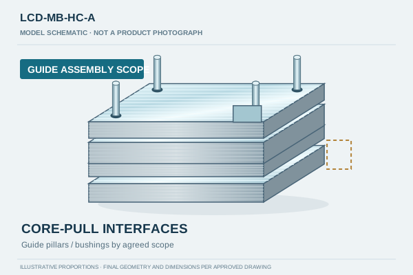
Machining + guide assembly
Drawing-specific machining with guide pillar and bushing assembly in the agreed supply scope. Purchased systems and additional assembly items are listed separately.
- Supply scope
- Machining with agreed guide pillar/bushing assembly
- Interface review
- Cylinder mounting interfaces; core movement and clearances; plate strength features; included components. Hydraulic cylinders are not automatically included.
- Overall capacity
- Footprint up to 1500×1200 mm; approximately 8 tonnes per set maximum, subject to drawing review
Cylinder mounting interfaces; core movement and clearances; plate strength features; included components. Hydraulic cylinders are not automatically included.
Request this optionGuide assembly refers to the agreed guide pillar and bushing work. Hot runner systems, hydraulic cylinders, rotation hardware and other purchased mechanisms are not automatically included.
Drawing and Quotation Checklist
- Supply cylinder mounting and core-movement interface information with the mold base drawing revision.
- Identify clearances, locating features and plate requirements around the moving core arrangement.
- State which cylinders, components and assembly operations are supplied by each party.
Include quantity, drawing revision, required inspection documents and delivery destination. Single-piece and small-batch inquiries are accepted.
Prepare a mold base inquiryInspection and Production Planning
Dimensional and CMM reports are available for agreed features, datums and tolerances. Overall capacity is up to 1500×1200 mm footprint and approximately 8 tonnes per set, subject to drawing review. Height, geometry, machining access and handling must be confirmed.
Typical production: 7–15 working days; large or complex projects 15–25 working days. Working days exclude weekends and statutory public holidays in China. The clock starts on the next working day after formal PO receipt, final drawing/specification approval and applicable deposit receipt are all completed. Transport time is separate.
Hydraulic Core-Pull Mold Bases Questions
Browse Other Mold Base Configurations
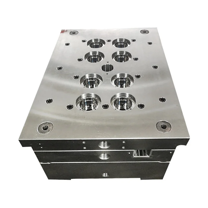 Product-form example
Custom Injection Mold Bases
Custom injection mold bases are reviewed around the plate stack, cavity/core interfaces and locating arrangement in your drawing. Quote machining alone or machining with the agreed guide pillar and guide bushing assembly.
Product details & quotation options →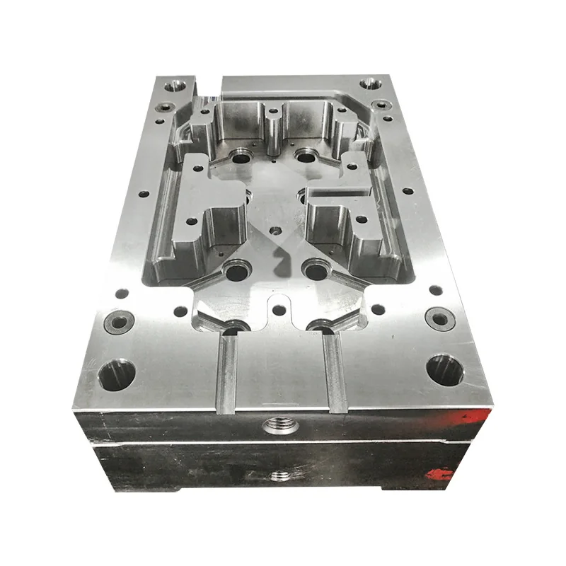 Product-form example
Hot Runner Mold Bases
Hot runner mold bases are machined around the specified manifold, nozzle and plate interfaces. Define the support and clearance features, the supplied plate stack and responsibility for the hot runner system before production.
Product details & quotation options →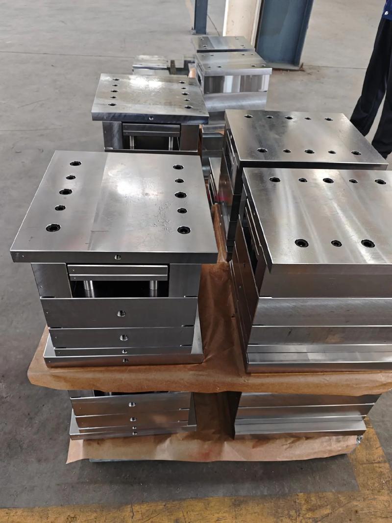 Product-form example
Two-Color & Multi-Color Mold Bases
Two-color and multi-color mold bases are reviewed against the machine interface, indexing or transfer arrangement and matched plate relationships. Define the locating datums and supplied hardware so the quotation covers the intended interfaces.
Product details & quotation options →