Made to drawing / Choose a manufacturing scope

Precision plate & mold base models.

Choose a steel grade and finish, or a mold base configuration and supply scope. Each model reference carries its specification into your inquiry. Finished dimensions remain drawing-specific.

30 plate grade/finish options14 mold base supply options11 steel grades7 mold configurations

44 model options · Made to drawing

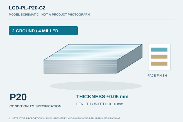
LCD-PL-P20-G2 face-finish schematic; illustrative geometry, dimensions per drawing
Original model schematic · illustrative geometry
LCD-PL-P20-G2

P20 Two-Side Ground + Four-Side Milled Plates

P20 Precision Tool Steel Plates · product details →

Precision grinding on two reference faces, with the four remaining faces milled. Thickness and length/width have separate tolerances.

Two ground reference faces / four milled faces

Length / width
±0.10 mm
Thickness
±0.05 mm
Buyer questions for this model →Finishing specifications & grade options →
View model specifications & supply scope
Material condition
Finish dimensions and material condition are agreed for the selected grade. Large plates and additional geometric requirements need drawing-specific review.
Size capacity
Regular: 100×100×20 to 800×600×300 mm. Maximum processing: 1200×800×400 mm, subject to grade, condition and finish review. The maximum is not an E1 tolerance envelope.
Parallelism
0.04 mm / 100 mm between the ground reference faces. Confirm any whole-span acceptance and additional geometric requirements on the drawing.
Reports
MTC, hardness and dimensional reports available. UT reports by request with an agreed scope.
Typical production
3–7 working days after the order-start conditions are completed. Transport time is separate.
Full technical scope →
Inquire about this model →
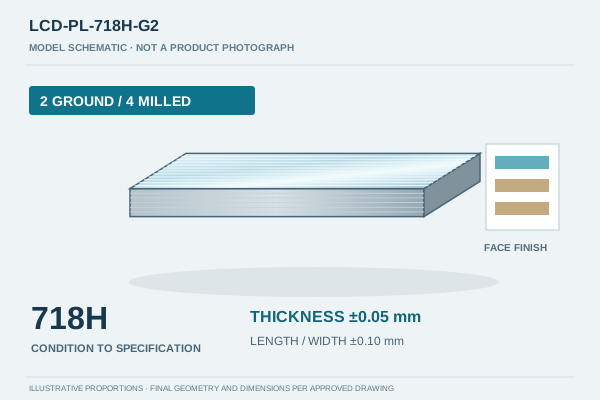
LCD-PL-718H-G2 face-finish schematic; illustrative geometry, dimensions per drawing
Original model schematic · illustrative geometry
LCD-PL-718H-G2

718H Two-Side Ground + Four-Side Milled Plates

718H Precision Tool Steel Plates · product details →

Precision grinding on two reference faces, with the four remaining faces milled. Thickness and length/width have separate tolerances.

Two ground reference faces / four milled faces

Length / width
±0.10 mm
Thickness
±0.05 mm
Buyer questions for this model →Finishing specifications & grade options →
View model specifications & supply scope
Material condition
Finish dimensions and material condition are agreed for the selected grade. Large plates and additional geometric requirements need drawing-specific review.
Size capacity
Regular: 100×100×20 to 800×600×300 mm. Maximum processing: 1200×800×400 mm, subject to grade, condition and finish review. The maximum is not an E1 tolerance envelope.
Parallelism
0.04 mm / 100 mm between the ground reference faces. Confirm any whole-span acceptance and additional geometric requirements on the drawing.
Reports
MTC, hardness and dimensional reports available. UT reports by request with an agreed scope.
Typical production
3–7 working days after the order-start conditions are completed. Transport time is separate.
Full technical scope →
Inquire about this model →
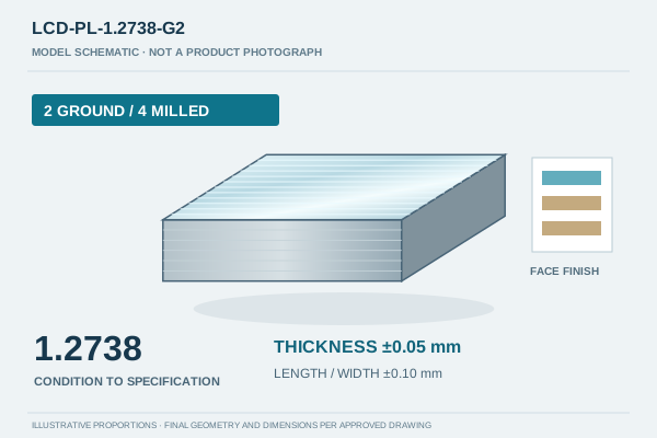
LCD-PL-1.2738-G2 face-finish schematic; illustrative geometry, dimensions per drawing
Original model schematic · illustrative geometry
LCD-PL-1.2738-G2

1.2738 Two-Side Ground + Four-Side Milled Plates

1.2738 Precision Tool Steel Plates · product details →

Precision grinding on two reference faces, with the four remaining faces milled. Thickness and length/width have separate tolerances.

Two ground reference faces / four milled faces

Length / width
±0.10 mm
Thickness
±0.05 mm
Buyer questions for this model →Finishing specifications & grade options →
View model specifications & supply scope
Material condition
Finish dimensions and material condition are agreed for the selected grade. Large plates and additional geometric requirements need drawing-specific review.
Size capacity
Regular: 100×100×20 to 800×600×300 mm. Maximum processing: 1200×800×400 mm, subject to grade, condition and finish review. The maximum is not an E1 tolerance envelope.
Parallelism
0.04 mm / 100 mm between the ground reference faces. Confirm any whole-span acceptance and additional geometric requirements on the drawing.
Reports
MTC, hardness and dimensional reports available. UT reports by request with an agreed scope.
Typical production
3–7 working days after the order-start conditions are completed. Transport time is separate.
Full technical scope →
Inquire about this model →
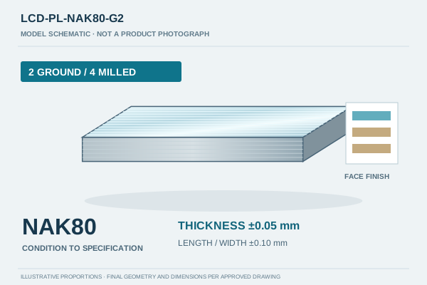
LCD-PL-NAK80-G2 face-finish schematic; illustrative geometry, dimensions per drawing
Original model schematic · illustrative geometry
LCD-PL-NAK80-G2

NAK80 Two-Side Ground + Four-Side Milled Plates

NAK80 Precision Tool Steel Plates · product details →

Precision grinding on two reference faces, with the four remaining faces milled. Thickness and length/width have separate tolerances.

Two ground reference faces / four milled faces

Length / width
±0.10 mm
Thickness
±0.05 mm
Buyer questions for this model →Finishing specifications & grade options →
View model specifications & supply scope
Material condition
Finish dimensions and material condition are agreed for the selected grade. Large plates and additional geometric requirements need drawing-specific review.
Size capacity
Regular: 100×100×20 to 800×600×300 mm. Maximum processing: 1200×800×400 mm, subject to grade, condition and finish review. The maximum is not an E1 tolerance envelope.
Parallelism
0.04 mm / 100 mm between the ground reference faces. Confirm any whole-span acceptance and additional geometric requirements on the drawing.
Reports
MTC, hardness and dimensional reports available. UT reports by request with an agreed scope.
Typical production
3–7 working days after the order-start conditions are completed. Transport time is separate.
Full technical scope →
Inquire about this model →
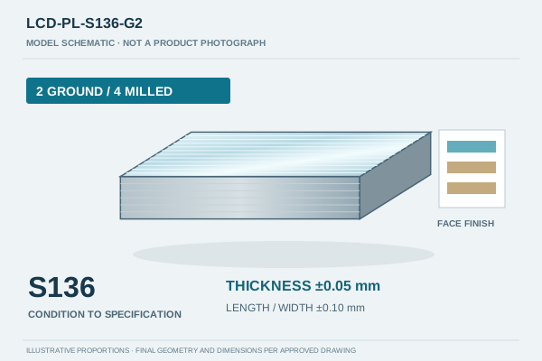
LCD-PL-S136-G2 face-finish schematic; illustrative geometry, dimensions per drawing
Original model schematic · illustrative geometry
LCD-PL-S136-G2

S136 Two-Side Ground + Four-Side Milled Plates

S136 Precision Tool Steel Plates · product details →

Precision grinding on two reference faces, with the four remaining faces milled. Thickness and length/width have separate tolerances.

Two ground reference faces / four milled faces

Length / width
±0.10 mm
Thickness
±0.05 mm
Buyer questions for this model →Finishing specifications & grade options →
View model specifications & supply scope
Material condition
Finish dimensions and material condition are agreed for the selected grade. Large plates and additional geometric requirements need drawing-specific review.
Size capacity
Regular: 100×100×20 to 800×600×300 mm. Maximum processing: 1200×800×400 mm, subject to grade, condition and finish review. The maximum is not an E1 tolerance envelope.
Parallelism
0.04 mm / 100 mm between the ground reference faces. Confirm any whole-span acceptance and additional geometric requirements on the drawing.
Reports
MTC, hardness and dimensional reports available. UT reports by request with an agreed scope.
Typical production
3–7 working days after the order-start conditions are completed. Transport time is separate.
Full technical scope →
Inquire about this model →
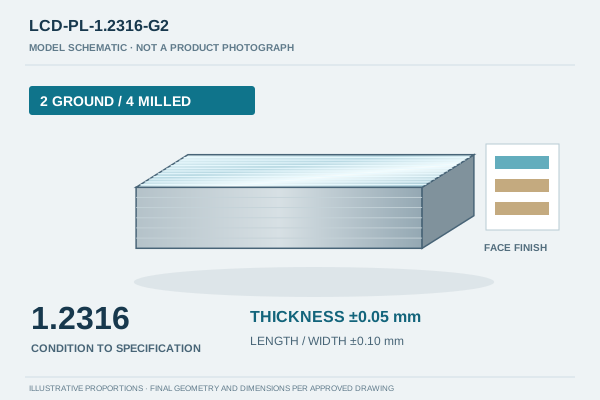
LCD-PL-1.2316-G2 face-finish schematic; illustrative geometry, dimensions per drawing
Original model schematic · illustrative geometry
LCD-PL-1.2316-G2

1.2316 Two-Side Ground + Four-Side Milled Plates

1.2316 Precision Tool Steel Plates · product details →

Precision grinding on two reference faces, with the four remaining faces milled. Thickness and length/width have separate tolerances.

Two ground reference faces / four milled faces

Length / width
±0.10 mm
Thickness
±0.05 mm
Buyer questions for this model →Finishing specifications & grade options →
View model specifications & supply scope
Material condition
Finish dimensions and material condition are agreed for the selected grade. Large plates and additional geometric requirements need drawing-specific review.
Size capacity
Regular: 100×100×20 to 800×600×300 mm. Maximum processing: 1200×800×400 mm, subject to grade, condition and finish review. The maximum is not an E1 tolerance envelope.
Parallelism
0.04 mm / 100 mm between the ground reference faces. Confirm any whole-span acceptance and additional geometric requirements on the drawing.
Reports
MTC, hardness and dimensional reports available. UT reports by request with an agreed scope.
Typical production
3–7 working days after the order-start conditions are completed. Transport time is separate.
Full technical scope →
Inquire about this model →
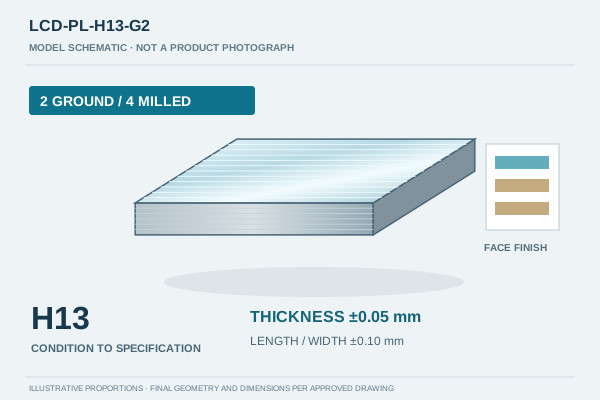
LCD-PL-H13-G2 face-finish schematic; illustrative geometry, dimensions per drawing
Original model schematic · illustrative geometry
LCD-PL-H13-G2

H13 Two-Side Ground + Four-Side Milled Plates

H13 Precision Tool Steel Plates · product details →

Precision grinding on two reference faces, with the four remaining faces milled. Thickness and length/width have separate tolerances.

Two ground reference faces / four milled faces

Length / width
±0.10 mm
Thickness
±0.05 mm
Buyer questions for this model →Finishing specifications & grade options →
View model specifications & supply scope
Material condition
Finish dimensions and material condition are agreed for the selected grade. Large plates and additional geometric requirements need drawing-specific review.
Size capacity
Regular: 100×100×20 to 800×600×300 mm. Maximum processing: 1200×800×400 mm, subject to grade, condition and finish review. The maximum is not an E1 tolerance envelope.
Parallelism
0.04 mm / 100 mm between the ground reference faces. Confirm any whole-span acceptance and additional geometric requirements on the drawing.
Reports
MTC, hardness and dimensional reports available. UT reports by request with an agreed scope.
Typical production
3–7 working days after the order-start conditions are completed. Transport time is separate.
Full technical scope →
Inquire about this model →
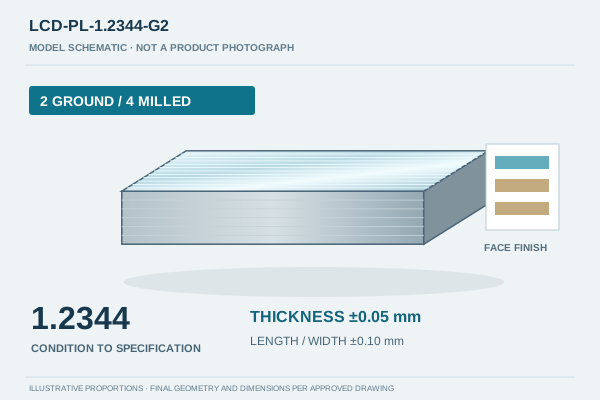
LCD-PL-1.2344-G2 face-finish schematic; illustrative geometry, dimensions per drawing
Original model schematic · illustrative geometry
LCD-PL-1.2344-G2

1.2344 Two-Side Ground + Four-Side Milled Plates

1.2344 Precision Tool Steel Plates · product details →

Precision grinding on two reference faces, with the four remaining faces milled. Thickness and length/width have separate tolerances.

Two ground reference faces / four milled faces

Length / width
±0.10 mm
Thickness
±0.05 mm
Buyer questions for this model →Finishing specifications & grade options →
View model specifications & supply scope
Material condition
Finish dimensions and material condition are agreed for the selected grade. Large plates and additional geometric requirements need drawing-specific review.
Size capacity
Regular: 100×100×20 to 800×600×300 mm. Maximum processing: 1200×800×400 mm, subject to grade, condition and finish review. The maximum is not an E1 tolerance envelope.
Parallelism
0.04 mm / 100 mm between the ground reference faces. Confirm any whole-span acceptance and additional geometric requirements on the drawing.
Reports
MTC, hardness and dimensional reports available. UT reports by request with an agreed scope.
Typical production
3–7 working days after the order-start conditions are completed. Transport time is separate.
Full technical scope →
Inquire about this model →
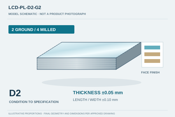
LCD-PL-D2-G2 face-finish schematic; illustrative geometry, dimensions per drawing
Original model schematic · illustrative geometry
LCD-PL-D2-G2

D2 Two-Side Ground + Four-Side Milled Plates

D2 Precision Tool Steel Plates · product details →

Precision grinding on two reference faces, with the four remaining faces milled. Thickness and length/width have separate tolerances.

Two ground reference faces / four milled faces

Length / width
±0.10 mm
Thickness
±0.05 mm
Buyer questions for this model →Finishing specifications & grade options →
View model specifications & supply scope
Material condition
Finish dimensions and material condition are agreed for the selected grade. Large plates and additional geometric requirements need drawing-specific review.
Size capacity
Regular: 100×100×20 to 800×600×300 mm. Maximum processing: 1200×800×400 mm, subject to grade, condition and finish review. The maximum is not an E1 tolerance envelope.
Parallelism
0.04 mm / 100 mm between the ground reference faces. Confirm any whole-span acceptance and additional geometric requirements on the drawing.
Reports
MTC, hardness and dimensional reports available. UT reports by request with an agreed scope.
Typical production
3–7 working days after the order-start conditions are completed. Transport time is separate.
Full technical scope →
Inquire about this model →
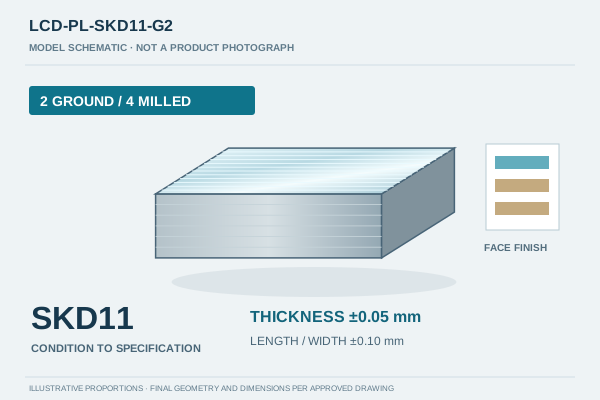
LCD-PL-SKD11-G2 face-finish schematic; illustrative geometry, dimensions per drawing
Original model schematic · illustrative geometry
LCD-PL-SKD11-G2

SKD11 Two-Side Ground + Four-Side Milled Plates

SKD11 Precision Tool Steel Plates · product details →

Precision grinding on two reference faces, with the four remaining faces milled. Thickness and length/width have separate tolerances.

Two ground reference faces / four milled faces

Length / width
±0.10 mm
Thickness
±0.05 mm
Buyer questions for this model →Finishing specifications & grade options →
View model specifications & supply scope
Material condition
Finish dimensions and material condition are agreed for the selected grade. Large plates and additional geometric requirements need drawing-specific review.
Size capacity
Regular: 100×100×20 to 800×600×300 mm. Maximum processing: 1200×800×400 mm, subject to grade, condition and finish review. The maximum is not an E1 tolerance envelope.
Parallelism
0.04 mm / 100 mm between the ground reference faces. Confirm any whole-span acceptance and additional geometric requirements on the drawing.
Reports
MTC, hardness and dimensional reports available. UT reports by request with an agreed scope.
Typical production
3–7 working days after the order-start conditions are completed. Transport time is separate.
Full technical scope →
Inquire about this model →
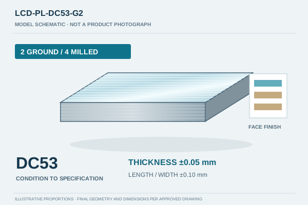
LCD-PL-DC53-G2 face-finish schematic; illustrative geometry, dimensions per drawing
Original model schematic · illustrative geometry
LCD-PL-DC53-G2

DC53 Two-Side Ground + Four-Side Milled Plates

DC53 Precision Tool Steel Plates · product details →

Precision grinding on two reference faces, with the four remaining faces milled. Thickness and length/width have separate tolerances.

Two ground reference faces / four milled faces

Length / width
±0.10 mm
Thickness
±0.05 mm
Buyer questions for this model →Finishing specifications & grade options →
View model specifications & supply scope
Material condition
Finish dimensions and material condition are agreed for the selected grade. Large plates and additional geometric requirements need drawing-specific review.
Size capacity
Regular: 100×100×20 to 800×600×300 mm. Maximum processing: 1200×800×400 mm, subject to grade, condition and finish review. The maximum is not an E1 tolerance envelope.
Parallelism
0.04 mm / 100 mm between the ground reference faces. Confirm any whole-span acceptance and additional geometric requirements on the drawing.
Reports
MTC, hardness and dimensional reports available. UT reports by request with an agreed scope.
Typical production
3–7 working days after the order-start conditions are completed. Transport time is separate.
Full technical scope →
Inquire about this model →
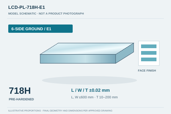
LCD-PL-718H-E1 face-finish schematic; illustrative geometry, dimensions per drawing
Original model schematic · illustrative geometry
LCD-PL-718H-E1

718H E1 Six-Side Precision Ground Plates

718H Precision Tool Steel Plates · product details →

All six faces precision ground under the published E1 grade, condition and size limits.

Six precision-ground faces / E1 limits apply

Length / width
±0.02 mm
Thickness
±0.02 mm
Buyer questions for this model →Finishing specifications & grade options →
View model specifications & supply scope
E1 material condition & dimensions
Pre-hardened 718H blocks within the E1 envelope: length and width each ≤600 mm; thickness 10–200 mm.
Parallelism
0.02 mm / 100 mm. Confirm any whole-span acceptance and additional geometric requirements on the drawing.
Reports
MTC, hardness and dimensional reports available. UT reports by request with an agreed scope.
Typical production
3–7 working days after the order-start conditions are completed. Transport time is separate.
Full technical scope →
Inquire about this model →
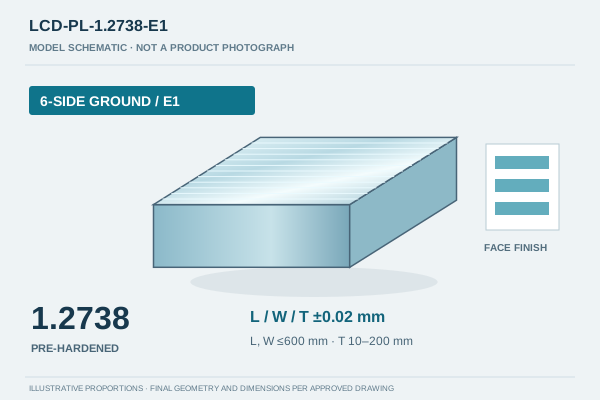
LCD-PL-1.2738-E1 face-finish schematic; illustrative geometry, dimensions per drawing
Original model schematic · illustrative geometry
LCD-PL-1.2738-E1

1.2738 E1 Six-Side Precision Ground Plates

1.2738 Precision Tool Steel Plates · product details →

All six faces precision ground under the published E1 grade, condition and size limits.

Six precision-ground faces / E1 limits apply

Length / width
±0.02 mm
Thickness
±0.02 mm
Buyer questions for this model →Finishing specifications & grade options →
View model specifications & supply scope
E1 material condition & dimensions
Pre-hardened 1.2738 blocks within the E1 envelope: length and width each ≤600 mm; thickness 10–200 mm.
Parallelism
0.02 mm / 100 mm. Confirm any whole-span acceptance and additional geometric requirements on the drawing.
Reports
MTC, hardness and dimensional reports available. UT reports by request with an agreed scope.
Typical production
3–7 working days after the order-start conditions are completed. Transport time is separate.
Full technical scope →
Inquire about this model →
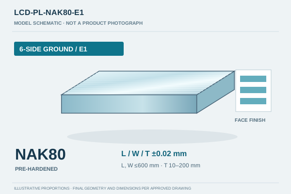
LCD-PL-NAK80-E1 face-finish schematic; illustrative geometry, dimensions per drawing
Original model schematic · illustrative geometry
LCD-PL-NAK80-E1

NAK80 E1 Six-Side Precision Ground Plates

NAK80 Precision Tool Steel Plates · product details →

All six faces precision ground under the published E1 grade, condition and size limits.

Six precision-ground faces / E1 limits apply

Length / width
±0.02 mm
Thickness
±0.02 mm
Buyer questions for this model →Finishing specifications & grade options →
View model specifications & supply scope
E1 material condition & dimensions
Pre-hardened NAK80 blocks within the E1 envelope: length and width each ≤600 mm; thickness 10–200 mm.
Parallelism
0.02 mm / 100 mm. Confirm any whole-span acceptance and additional geometric requirements on the drawing.
Reports
MTC, hardness and dimensional reports available. UT reports by request with an agreed scope.
Typical production
3–7 working days after the order-start conditions are completed. Transport time is separate.
Full technical scope →
Inquire about this model →
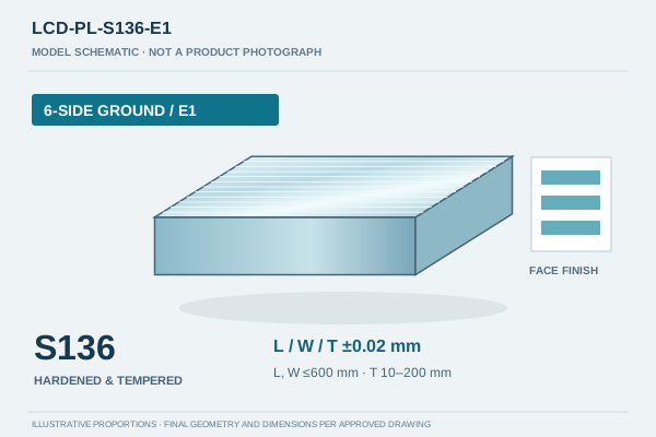
LCD-PL-S136-E1 face-finish schematic; illustrative geometry, dimensions per drawing
Original model schematic · illustrative geometry
LCD-PL-S136-E1

S136 E1 Six-Side Precision Ground Plates

S136 Precision Tool Steel Plates · product details →

All six faces precision ground under the published E1 grade, condition and size limits.

Six precision-ground faces / E1 limits apply

Length / width
±0.02 mm
Thickness
±0.02 mm
Buyer questions for this model →Finishing specifications & grade options →
View model specifications & supply scope
E1 material condition & dimensions
Hardened and tempered S136 blocks within the E1 envelope: length and width each ≤600 mm; thickness 10–200 mm.
Parallelism
0.02 mm / 100 mm. Confirm any whole-span acceptance and additional geometric requirements on the drawing.
Reports
MTC, hardness and dimensional reports available. UT reports by request with an agreed scope.
Typical production
3–7 working days after the order-start conditions are completed. Transport time is separate.
Full technical scope →
Inquire about this model →
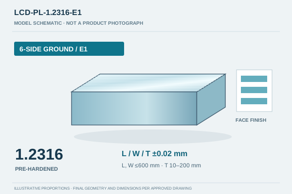
LCD-PL-1.2316-E1 face-finish schematic; illustrative geometry, dimensions per drawing
Original model schematic · illustrative geometry
LCD-PL-1.2316-E1

1.2316 E1 Six-Side Precision Ground Plates

1.2316 Precision Tool Steel Plates · product details →

All six faces precision ground under the published E1 grade, condition and size limits.

Six precision-ground faces / E1 limits apply

Length / width
±0.02 mm
Thickness
±0.02 mm
Buyer questions for this model →Finishing specifications & grade options →
View model specifications & supply scope
E1 material condition & dimensions
Pre-hardened 1.2316 blocks within the E1 envelope: length and width each ≤600 mm; thickness 10–200 mm.
Parallelism
0.02 mm / 100 mm. Confirm any whole-span acceptance and additional geometric requirements on the drawing.
Reports
MTC, hardness and dimensional reports available. UT reports by request with an agreed scope.
Typical production
3–7 working days after the order-start conditions are completed. Transport time is separate.
Full technical scope →
Inquire about this model →
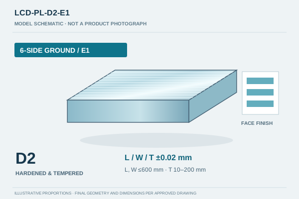
LCD-PL-D2-E1 face-finish schematic; illustrative geometry, dimensions per drawing
Original model schematic · illustrative geometry
LCD-PL-D2-E1

D2 E1 Six-Side Precision Ground Plates

D2 Precision Tool Steel Plates · product details →

All six faces precision ground under the published E1 grade, condition and size limits.

Six precision-ground faces / E1 limits apply

Length / width
±0.02 mm
Thickness
±0.02 mm
Buyer questions for this model →Finishing specifications & grade options →
View model specifications & supply scope
E1 material condition & dimensions
Hardened and tempered D2 blocks within the E1 envelope: length and width each ≤600 mm; thickness 10–200 mm.
Parallelism
0.02 mm / 100 mm. Confirm any whole-span acceptance and additional geometric requirements on the drawing.
Reports
MTC, hardness and dimensional reports available. UT reports by request with an agreed scope.
Typical production
3–7 working days after the order-start conditions are completed. Transport time is separate.
Full technical scope →
Inquire about this model →
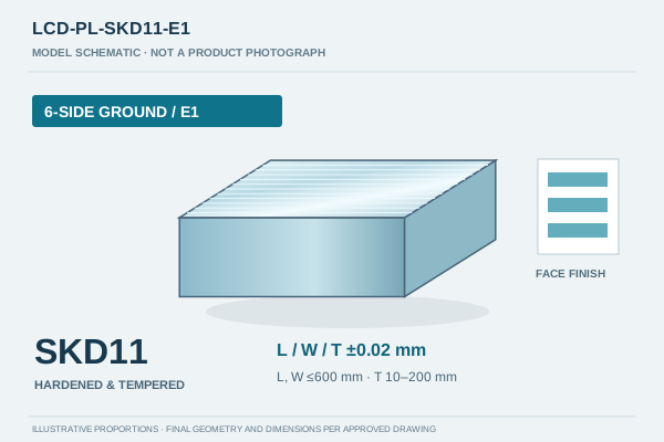
LCD-PL-SKD11-E1 face-finish schematic; illustrative geometry, dimensions per drawing
Original model schematic · illustrative geometry
LCD-PL-SKD11-E1

SKD11 E1 Six-Side Precision Ground Plates

SKD11 Precision Tool Steel Plates · product details →

All six faces precision ground under the published E1 grade, condition and size limits.

Six precision-ground faces / E1 limits apply

Length / width
±0.02 mm
Thickness
±0.02 mm
Buyer questions for this model →Finishing specifications & grade options →
View model specifications & supply scope
E1 material condition & dimensions
Hardened and tempered SKD11 blocks within the E1 envelope: length and width each ≤600 mm; thickness 10–200 mm.
Parallelism
0.02 mm / 100 mm. Confirm any whole-span acceptance and additional geometric requirements on the drawing.
Reports
MTC, hardness and dimensional reports available. UT reports by request with an agreed scope.
Typical production
3–7 working days after the order-start conditions are completed. Transport time is separate.
Full technical scope →
Inquire about this model →
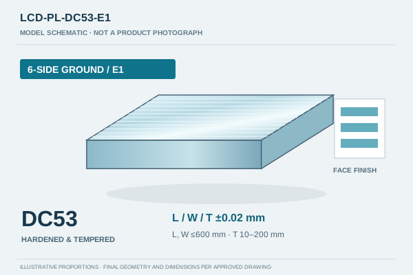
LCD-PL-DC53-E1 face-finish schematic; illustrative geometry, dimensions per drawing
Original model schematic · illustrative geometry
LCD-PL-DC53-E1

DC53 E1 Six-Side Precision Ground Plates

DC53 Precision Tool Steel Plates · product details →

All six faces precision ground under the published E1 grade, condition and size limits.

Six precision-ground faces / E1 limits apply

Length / width
±0.02 mm
Thickness
±0.02 mm
Buyer questions for this model →Finishing specifications & grade options →
View model specifications & supply scope
E1 material condition & dimensions
Hardened and tempered DC53 blocks within the E1 envelope: length and width each ≤600 mm; thickness 10–200 mm.
Parallelism
0.02 mm / 100 mm. Confirm any whole-span acceptance and additional geometric requirements on the drawing.
Reports
MTC, hardness and dimensional reports available. UT reports by request with an agreed scope.
Typical production
3–7 working days after the order-start conditions are completed. Transport time is separate.
Full technical scope →
Inquire about this model →
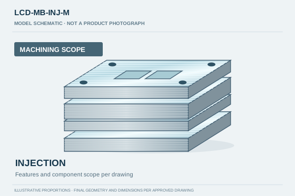
LCD-MB-INJ-M configuration and supply-scope schematic; final layout per drawing
Original model schematic · illustrative geometry
LCD-MB-INJ-M

Custom Injection Mold Bases — Machining Scope

Custom Injection Mold Bases · product details →

Drawing-specific plate and feature machining. The quotation identifies supplied parts and inspection; assembly is separately defined.

Drawing-specific plate & feature machining

Supply scope
Machining scope
Configuration
injection
Buyer questions for this model →
View model specifications & supply scope
Drawing review
Plate stack and datums; cavity/core interfaces; guide pillar and bushing scope; water channel layout.
Manufacturing scope
CNC rough/finish milling, grinding, drilling, boring, tapping and water-channel machining as specified. Plate and feature machining is quoted to the drawing. Supplied components and any assembly are identified separately.
Overall capacity
Footprint up to 1500×1200 mm; approximately 8 tonnes per set maximum, subject to drawing review. Overall height and geometry require review.
Inspection
Dimensional and CMM reports available for agreed features, datums and tolerances.
Purchased systems
Hot runner systems, hydraulic cylinders, rotation hardware and other bought-in mechanisms are not automatically included.
Typical production
7–15 working days; large or complex projects 15–25 working days after all order-start conditions are completed. Transport time is separate.
Full technical scope →
Inquire about this model →
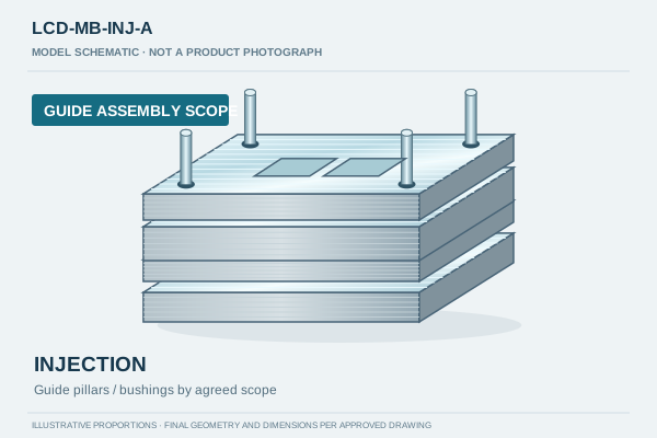
LCD-MB-INJ-A configuration and supply-scope schematic; final layout per drawing
Original model schematic · illustrative geometry
LCD-MB-INJ-A

Custom Injection Mold Bases — Machining & Guide Assembly

Custom Injection Mold Bases · product details →

Drawing-specific machining with guide pillar and bushing assembly in the agreed supply scope. Purchased systems and additional assembly items are listed separately.

Machining + guide pillar/bushing assembly

Supply scope
Guide assembly included as agreed
Configuration
injection
Buyer questions for this model →
View model specifications & supply scope
Drawing review
Plate stack and datums; cavity/core interfaces; guide pillar and bushing scope; water channel layout.
Manufacturing scope
CNC rough/finish milling, grinding, drilling, boring, tapping and water-channel machining as specified. Guide pillar and bushing assembly is included in the agreed quotation scope. Other supplied components and assembly items are listed separately.
Overall capacity
Footprint up to 1500×1200 mm; approximately 8 tonnes per set maximum, subject to drawing review. Overall height and geometry require review.
Inspection
Dimensional and CMM reports available for agreed features, datums and tolerances.
Purchased systems
Hot runner systems, hydraulic cylinders, rotation hardware and other bought-in mechanisms are not automatically included.
Typical production
7–15 working days; large or complex projects 15–25 working days after all order-start conditions are completed. Transport time is separate.
Full technical scope →
Inquire about this model →
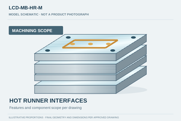
LCD-MB-HR-M configuration and supply-scope schematic; final layout per drawing
Original model schematic · illustrative geometry
LCD-MB-HR-M

Hot Runner Mold Bases — Machining Scope

Hot Runner Mold Bases · product details →

Drawing-specific plate and feature machining. The quotation identifies supplied parts and inspection; assembly is separately defined.

Drawing-specific plate & feature machining

Supply scope
Machining scope
Configuration
hot runner
Buyer questions for this model →
View model specifications & supply scope
Drawing review
Manifold and nozzle interfaces; clearance and support features; plate layout; responsibility for the hot runner system. Hot runner hardware is not automatically included.
Manufacturing scope
CNC rough/finish milling, grinding, drilling, boring, tapping and water-channel machining as specified. Plate and feature machining is quoted to the drawing. Supplied components and any assembly are identified separately.
Overall capacity
Footprint up to 1500×1200 mm; approximately 8 tonnes per set maximum, subject to drawing review. Overall height and geometry require review.
Inspection
Dimensional and CMM reports available for agreed features, datums and tolerances.
Purchased systems
Hot runner systems, hydraulic cylinders, rotation hardware and other bought-in mechanisms are not automatically included.
Typical production
7–15 working days; large or complex projects 15–25 working days after all order-start conditions are completed. Transport time is separate.
Full technical scope →
Inquire about this model →
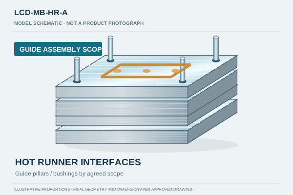
LCD-MB-HR-A configuration and supply-scope schematic; final layout per drawing
Original model schematic · illustrative geometry
LCD-MB-HR-A

Hot Runner Mold Bases — Machining & Guide Assembly

Hot Runner Mold Bases · product details →

Drawing-specific machining with guide pillar and bushing assembly in the agreed supply scope. Purchased systems and additional assembly items are listed separately.

Machining + guide pillar/bushing assembly

Supply scope
Guide assembly included as agreed
Configuration
hot runner
Buyer questions for this model →
View model specifications & supply scope
Drawing review
Manifold and nozzle interfaces; clearance and support features; plate layout; responsibility for the hot runner system. Hot runner hardware is not automatically included.
Manufacturing scope
CNC rough/finish milling, grinding, drilling, boring, tapping and water-channel machining as specified. Guide pillar and bushing assembly is included in the agreed quotation scope. Other supplied components and assembly items are listed separately.
Overall capacity
Footprint up to 1500×1200 mm; approximately 8 tonnes per set maximum, subject to drawing review. Overall height and geometry require review.
Inspection
Dimensional and CMM reports available for agreed features, datums and tolerances.
Purchased systems
Hot runner systems, hydraulic cylinders, rotation hardware and other bought-in mechanisms are not automatically included.
Typical production
7–15 working days; large or complex projects 15–25 working days after all order-start conditions are completed. Transport time is separate.
Full technical scope →
Inquire about this model →
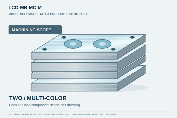
LCD-MB-MC-M configuration and supply-scope schematic; final layout per drawing
Original model schematic · illustrative geometry
LCD-MB-MC-M

Two-Color & Multi-Color Mold Bases — Machining Scope

Two-Color & Multi-Color Mold Bases · product details →

Drawing-specific plate and feature machining. The quotation identifies supplied parts and inspection; assembly is separately defined.

Drawing-specific plate & feature machining

Supply scope
Machining scope
Configuration
multi color
Buyer questions for this model →
View model specifications & supply scope
Drawing review
Machine interface; indexing or transfer arrangement; locating datums; matched plate and component scope. Rotation hardware is not automatically included.
Manufacturing scope
CNC rough/finish milling, grinding, drilling, boring, tapping and water-channel machining as specified. Plate and feature machining is quoted to the drawing. Supplied components and any assembly are identified separately.
Overall capacity
Footprint up to 1500×1200 mm; approximately 8 tonnes per set maximum, subject to drawing review. Overall height and geometry require review.
Inspection
Dimensional and CMM reports available for agreed features, datums and tolerances.
Purchased systems
Hot runner systems, hydraulic cylinders, rotation hardware and other bought-in mechanisms are not automatically included.
Typical production
7–15 working days; large or complex projects 15–25 working days after all order-start conditions are completed. Transport time is separate.
Full technical scope →
Inquire about this model →
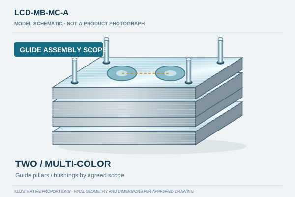
LCD-MB-MC-A configuration and supply-scope schematic; final layout per drawing
Original model schematic · illustrative geometry
LCD-MB-MC-A

Two-Color & Multi-Color Mold Bases — Machining & Guide Assembly

Two-Color & Multi-Color Mold Bases · product details →

Drawing-specific machining with guide pillar and bushing assembly in the agreed supply scope. Purchased systems and additional assembly items are listed separately.

Machining + guide pillar/bushing assembly

Supply scope
Guide assembly included as agreed
Configuration
multi color
Buyer questions for this model →
View model specifications & supply scope
Drawing review
Machine interface; indexing or transfer arrangement; locating datums; matched plate and component scope. Rotation hardware is not automatically included.
Manufacturing scope
CNC rough/finish milling, grinding, drilling, boring, tapping and water-channel machining as specified. Guide pillar and bushing assembly is included in the agreed quotation scope. Other supplied components and assembly items are listed separately.
Overall capacity
Footprint up to 1500×1200 mm; approximately 8 tonnes per set maximum, subject to drawing review. Overall height and geometry require review.
Inspection
Dimensional and CMM reports available for agreed features, datums and tolerances.
Purchased systems
Hot runner systems, hydraulic cylinders, rotation hardware and other bought-in mechanisms are not automatically included.
Typical production
7–15 working days; large or complex projects 15–25 working days after all order-start conditions are completed. Transport time is separate.
Full technical scope →
Inquire about this model →
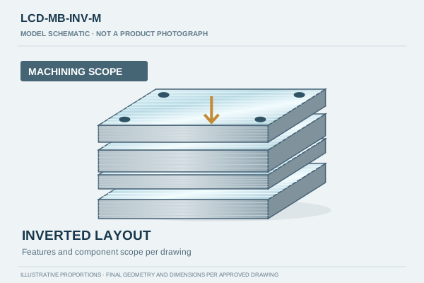
LCD-MB-INV-M configuration and supply-scope schematic; final layout per drawing
Original model schematic · illustrative geometry
LCD-MB-INV-M

Inverted Mold Bases — Machining Scope

Inverted Mold Bases · product details →

Drawing-specific plate and feature machining. The quotation identifies supplied parts and inspection; assembly is separately defined.

Drawing-specific plate & feature machining

Supply scope
Machining scope
Configuration
inverted
Buyer questions for this model →
View model specifications & supply scope
Drawing review
Installation direction; fixed/moving-side interfaces; ejection layout; guide arrangement and assembly requirements.
Manufacturing scope
CNC rough/finish milling, grinding, drilling, boring, tapping and water-channel machining as specified. Plate and feature machining is quoted to the drawing. Supplied components and any assembly are identified separately.
Overall capacity
Footprint up to 1500×1200 mm; approximately 8 tonnes per set maximum, subject to drawing review. Overall height and geometry require review.
Inspection
Dimensional and CMM reports available for agreed features, datums and tolerances.
Purchased systems
Hot runner systems, hydraulic cylinders, rotation hardware and other bought-in mechanisms are not automatically included.
Typical production
7–15 working days; large or complex projects 15–25 working days after all order-start conditions are completed. Transport time is separate.
Full technical scope →
Inquire about this model →
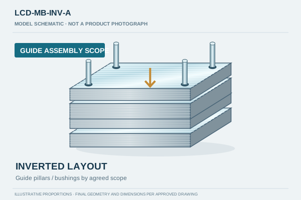
LCD-MB-INV-A configuration and supply-scope schematic; final layout per drawing
Original model schematic · illustrative geometry
LCD-MB-INV-A

Inverted Mold Bases — Machining & Guide Assembly

Inverted Mold Bases · product details →

Drawing-specific machining with guide pillar and bushing assembly in the agreed supply scope. Purchased systems and additional assembly items are listed separately.

Machining + guide pillar/bushing assembly

Supply scope
Guide assembly included as agreed
Configuration
inverted
Buyer questions for this model →
View model specifications & supply scope
Drawing review
Installation direction; fixed/moving-side interfaces; ejection layout; guide arrangement and assembly requirements.
Manufacturing scope
CNC rough/finish milling, grinding, drilling, boring, tapping and water-channel machining as specified. Guide pillar and bushing assembly is included in the agreed quotation scope. Other supplied components and assembly items are listed separately.
Overall capacity
Footprint up to 1500×1200 mm; approximately 8 tonnes per set maximum, subject to drawing review. Overall height and geometry require review.
Inspection
Dimensional and CMM reports available for agreed features, datums and tolerances.
Purchased systems
Hot runner systems, hydraulic cylinders, rotation hardware and other bought-in mechanisms are not automatically included.
Typical production
7–15 working days; large or complex projects 15–25 working days after all order-start conditions are completed. Transport time is separate.
Full technical scope →
Inquire about this model →
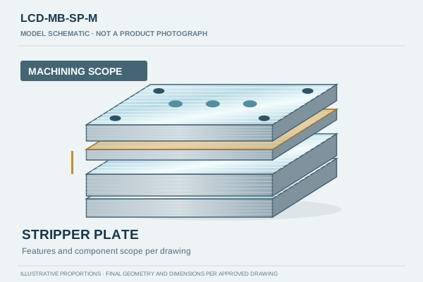
LCD-MB-SP-M configuration and supply-scope schematic; final layout per drawing
Original model schematic · illustrative geometry
LCD-MB-SP-M

Stripper Plate Mold Bases — Machining Scope

Stripper Plate Mold Bases · product details →

Drawing-specific plate and feature machining. The quotation identifies supplied parts and inspection; assembly is separately defined.

Drawing-specific plate & feature machining

Supply scope
Machining scope
Configuration
stripper plate
Buyer questions for this model →
View model specifications & supply scope
Drawing review
Stripper travel; guide locations; plate clearances; return arrangement; agreed assembly scope.
Manufacturing scope
CNC rough/finish milling, grinding, drilling, boring, tapping and water-channel machining as specified. Plate and feature machining is quoted to the drawing. Supplied components and any assembly are identified separately.
Overall capacity
Footprint up to 1500×1200 mm; approximately 8 tonnes per set maximum, subject to drawing review. Overall height and geometry require review.
Inspection
Dimensional and CMM reports available for agreed features, datums and tolerances.
Purchased systems
Hot runner systems, hydraulic cylinders, rotation hardware and other bought-in mechanisms are not automatically included.
Typical production
7–15 working days; large or complex projects 15–25 working days after all order-start conditions are completed. Transport time is separate.
Full technical scope →
Inquire about this model →
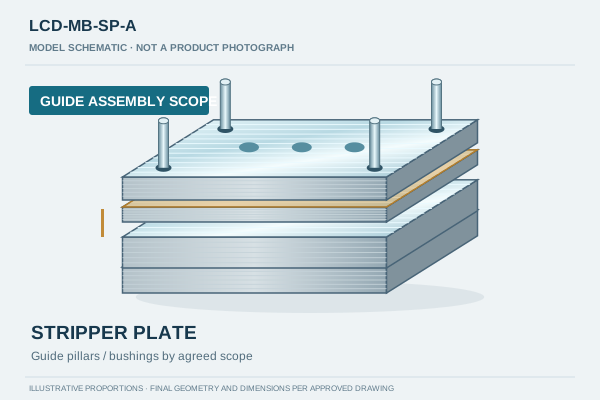
LCD-MB-SP-A configuration and supply-scope schematic; final layout per drawing
Original model schematic · illustrative geometry
LCD-MB-SP-A

Stripper Plate Mold Bases — Machining & Guide Assembly

Stripper Plate Mold Bases · product details →

Drawing-specific machining with guide pillar and bushing assembly in the agreed supply scope. Purchased systems and additional assembly items are listed separately.

Machining + guide pillar/bushing assembly

Supply scope
Guide assembly included as agreed
Configuration
stripper plate
Buyer questions for this model →
View model specifications & supply scope
Drawing review
Stripper travel; guide locations; plate clearances; return arrangement; agreed assembly scope.
Manufacturing scope
CNC rough/finish milling, grinding, drilling, boring, tapping and water-channel machining as specified. Guide pillar and bushing assembly is included in the agreed quotation scope. Other supplied components and assembly items are listed separately.
Overall capacity
Footprint up to 1500×1200 mm; approximately 8 tonnes per set maximum, subject to drawing review. Overall height and geometry require review.
Inspection
Dimensional and CMM reports available for agreed features, datums and tolerances.
Purchased systems
Hot runner systems, hydraulic cylinders, rotation hardware and other bought-in mechanisms are not automatically included.
Typical production
7–15 working days; large or complex projects 15–25 working days after all order-start conditions are completed. Transport time is separate.
Full technical scope →
Inquire about this model →
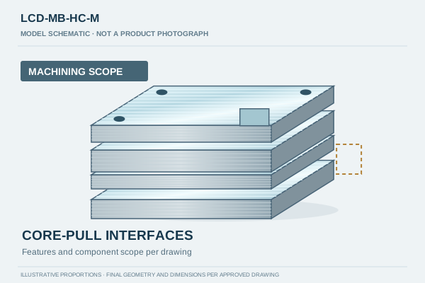
LCD-MB-HC-M configuration and supply-scope schematic; final layout per drawing
Original model schematic · illustrative geometry
LCD-MB-HC-M

Hydraulic Core-Pull Mold Bases — Machining Scope

Hydraulic Core-Pull Mold Bases · product details →

Drawing-specific plate and feature machining. The quotation identifies supplied parts and inspection; assembly is separately defined.

Drawing-specific plate & feature machining

Supply scope
Machining scope
Configuration
hydraulic core pull
Buyer questions for this model →
View model specifications & supply scope
Drawing review
Cylinder mounting interfaces; core movement and clearances; plate strength features; included components. Hydraulic cylinders are not automatically included.
Manufacturing scope
CNC rough/finish milling, grinding, drilling, boring, tapping and water-channel machining as specified. Plate and feature machining is quoted to the drawing. Supplied components and any assembly are identified separately.
Overall capacity
Footprint up to 1500×1200 mm; approximately 8 tonnes per set maximum, subject to drawing review. Overall height and geometry require review.
Inspection
Dimensional and CMM reports available for agreed features, datums and tolerances.
Purchased systems
Hot runner systems, hydraulic cylinders, rotation hardware and other bought-in mechanisms are not automatically included.
Typical production
7–15 working days; large or complex projects 15–25 working days after all order-start conditions are completed. Transport time is separate.
Full technical scope →
Inquire about this model →
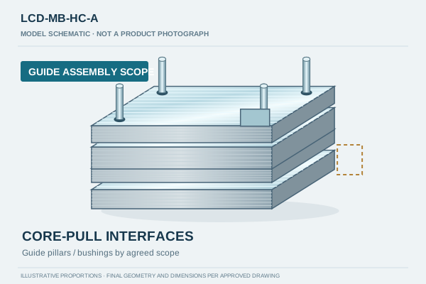
LCD-MB-HC-A configuration and supply-scope schematic; final layout per drawing
Original model schematic · illustrative geometry
LCD-MB-HC-A

Hydraulic Core-Pull Mold Bases — Machining & Guide Assembly

Hydraulic Core-Pull Mold Bases · product details →

Drawing-specific machining with guide pillar and bushing assembly in the agreed supply scope. Purchased systems and additional assembly items are listed separately.

Machining + guide pillar/bushing assembly

Supply scope
Guide assembly included as agreed
Configuration
hydraulic core pull
Buyer questions for this model →
View model specifications & supply scope
Drawing review
Cylinder mounting interfaces; core movement and clearances; plate strength features; included components. Hydraulic cylinders are not automatically included.
Manufacturing scope
CNC rough/finish milling, grinding, drilling, boring, tapping and water-channel machining as specified. Guide pillar and bushing assembly is included in the agreed quotation scope. Other supplied components and assembly items are listed separately.
Overall capacity
Footprint up to 1500×1200 mm; approximately 8 tonnes per set maximum, subject to drawing review. Overall height and geometry require review.
Inspection
Dimensional and CMM reports available for agreed features, datums and tolerances.
Purchased systems
Hot runner systems, hydraulic cylinders, rotation hardware and other bought-in mechanisms are not automatically included.
Typical production
7–15 working days; large or complex projects 15–25 working days after all order-start conditions are completed. Transport time is separate.
Full technical scope →
Inquire about this model →
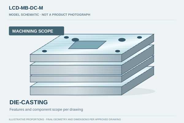
LCD-MB-DC-M configuration and supply-scope schematic; final layout per drawing
Original model schematic · illustrative geometry
LCD-MB-DC-M

Custom Die-Casting Mold Bases — Machining Scope

Custom Die-Casting Mold Bases · product details →

Drawing-specific plate and feature machining. The quotation identifies supplied parts and inspection; assembly is separately defined.

Drawing-specific plate & feature machining

Supply scope
Machining scope
Configuration
die casting
Buyer questions for this model →
View model specifications & supply scope
Drawing review
Machine mounting interface; slide and guide layout; water channels; material condition; inspection datums and assembly scope.
Manufacturing scope
CNC rough/finish milling, grinding, drilling, boring, tapping and water-channel machining as specified. Plate and feature machining is quoted to the drawing. Supplied components and any assembly are identified separately.
Overall capacity
Footprint up to 1500×1200 mm; approximately 8 tonnes per set maximum, subject to drawing review. Overall height and geometry require review.
Inspection
Dimensional and CMM reports available for agreed features, datums and tolerances.
Purchased systems
Hot runner systems, hydraulic cylinders, rotation hardware and other bought-in mechanisms are not automatically included.
Typical production
7–15 working days; large or complex projects 15–25 working days after all order-start conditions are completed. Transport time is separate.
Full technical scope →
Inquire about this model →
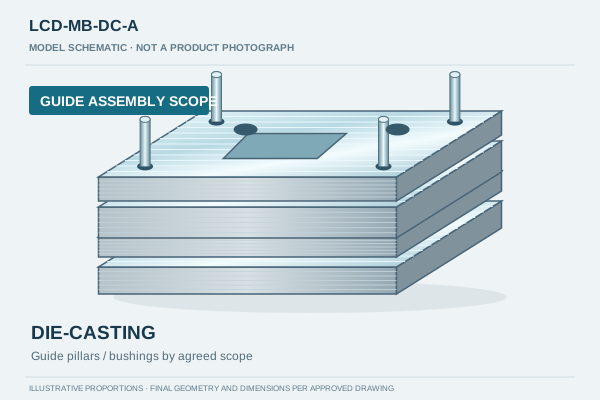
LCD-MB-DC-A configuration and supply-scope schematic; final layout per drawing
Original model schematic · illustrative geometry
LCD-MB-DC-A

Custom Die-Casting Mold Bases — Machining & Guide Assembly

Custom Die-Casting Mold Bases · product details →

Drawing-specific machining with guide pillar and bushing assembly in the agreed supply scope. Purchased systems and additional assembly items are listed separately.

Machining + guide pillar/bushing assembly

Supply scope
Guide assembly included as agreed
Configuration
die casting
Buyer questions for this model →
View model specifications & supply scope
Drawing review
Machine mounting interface; slide and guide layout; water channels; material condition; inspection datums and assembly scope.
Manufacturing scope
CNC rough/finish milling, grinding, drilling, boring, tapping and water-channel machining as specified. Guide pillar and bushing assembly is included in the agreed quotation scope. Other supplied components and assembly items are listed separately.
Overall capacity
Footprint up to 1500×1200 mm; approximately 8 tonnes per set maximum, subject to drawing review. Overall height and geometry require review.
Inspection
Dimensional and CMM reports available for agreed features, datums and tolerances.
Purchased systems
Hot runner systems, hydraulic cylinders, rotation hardware and other bought-in mechanisms are not automatically included.
Typical production
7–15 working days; large or complex projects 15–25 working days after all order-start conditions are completed. Transport time is separate.
Full technical scope →
Inquire about this model →
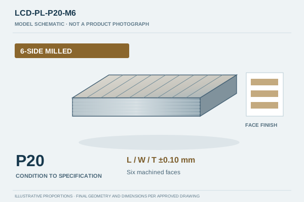
LCD-PL-P20-M6 face-finish schematic; illustrative geometry, dimensions per drawing
Original model schematic · illustrative geometry
LCD-PL-P20-M6

P20 Six-Side Precision Milled Plates

P20 Precision Tool Steel Plates · product details →

All six faces precision milled to the agreed finished dimensions. Use the drawing to identify any additional grinding requirements.

Six precision-milled faces

Length / width
±0.10 mm
Thickness
±0.10 mm
Buyer questions for this model →Finishing specifications & grade options →
View model specifications & supply scope
Material condition
Finish dimensions and material condition are agreed for the selected grade. Large plates and additional geometric requirements need drawing-specific review.
Size capacity
Regular: 100×100×20 to 800×600×300 mm. Maximum processing: 1200×800×400 mm, subject to grade, condition and finish review. The maximum is not an E1 tolerance envelope.
Parallelism
0.08 mm / 100 mm. Confirm any whole-span acceptance and additional geometric requirements on the drawing.
Reports
MTC, hardness and dimensional reports available. UT reports by request with an agreed scope.
Typical production
3–7 working days after the order-start conditions are completed. Transport time is separate.
Full technical scope →
Inquire about this model →
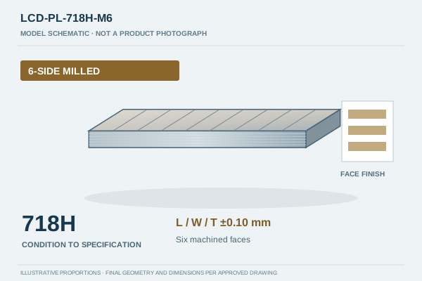
LCD-PL-718H-M6 face-finish schematic; illustrative geometry, dimensions per drawing
Original model schematic · illustrative geometry
LCD-PL-718H-M6

718H Six-Side Precision Milled Plates

718H Precision Tool Steel Plates · product details →

All six faces precision milled to the agreed finished dimensions. Use the drawing to identify any additional grinding requirements.

Six precision-milled faces

Length / width
±0.10 mm
Thickness
±0.10 mm
Buyer questions for this model →Finishing specifications & grade options →
View model specifications & supply scope
Material condition
Finish dimensions and material condition are agreed for the selected grade. Large plates and additional geometric requirements need drawing-specific review.
Size capacity
Regular: 100×100×20 to 800×600×300 mm. Maximum processing: 1200×800×400 mm, subject to grade, condition and finish review. The maximum is not an E1 tolerance envelope.
Parallelism
0.08 mm / 100 mm. Confirm any whole-span acceptance and additional geometric requirements on the drawing.
Reports
MTC, hardness and dimensional reports available. UT reports by request with an agreed scope.
Typical production
3–7 working days after the order-start conditions are completed. Transport time is separate.
Full technical scope →
Inquire about this model →
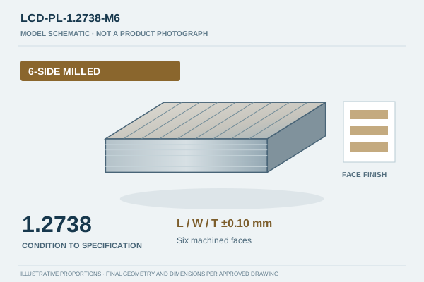
LCD-PL-1.2738-M6 face-finish schematic; illustrative geometry, dimensions per drawing
Original model schematic · illustrative geometry
LCD-PL-1.2738-M6

1.2738 Six-Side Precision Milled Plates

1.2738 Precision Tool Steel Plates · product details →

All six faces precision milled to the agreed finished dimensions. Use the drawing to identify any additional grinding requirements.

Six precision-milled faces

Length / width
±0.10 mm
Thickness
±0.10 mm
Buyer questions for this model →Finishing specifications & grade options →
View model specifications & supply scope
Material condition
Finish dimensions and material condition are agreed for the selected grade. Large plates and additional geometric requirements need drawing-specific review.
Size capacity
Regular: 100×100×20 to 800×600×300 mm. Maximum processing: 1200×800×400 mm, subject to grade, condition and finish review. The maximum is not an E1 tolerance envelope.
Parallelism
0.08 mm / 100 mm. Confirm any whole-span acceptance and additional geometric requirements on the drawing.
Reports
MTC, hardness and dimensional reports available. UT reports by request with an agreed scope.
Typical production
3–7 working days after the order-start conditions are completed. Transport time is separate.
Full technical scope →
Inquire about this model →
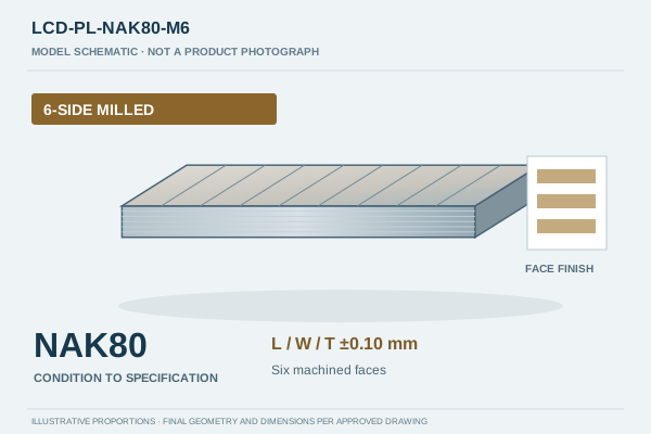
LCD-PL-NAK80-M6 face-finish schematic; illustrative geometry, dimensions per drawing
Original model schematic · illustrative geometry
LCD-PL-NAK80-M6

NAK80 Six-Side Precision Milled Plates

NAK80 Precision Tool Steel Plates · product details →

All six faces precision milled to the agreed finished dimensions. Use the drawing to identify any additional grinding requirements.

Six precision-milled faces

Length / width
±0.10 mm
Thickness
±0.10 mm
Buyer questions for this model →Finishing specifications & grade options →
View model specifications & supply scope
Material condition
Finish dimensions and material condition are agreed for the selected grade. Large plates and additional geometric requirements need drawing-specific review.
Size capacity
Regular: 100×100×20 to 800×600×300 mm. Maximum processing: 1200×800×400 mm, subject to grade, condition and finish review. The maximum is not an E1 tolerance envelope.
Parallelism
0.08 mm / 100 mm. Confirm any whole-span acceptance and additional geometric requirements on the drawing.
Reports
MTC, hardness and dimensional reports available. UT reports by request with an agreed scope.
Typical production
3–7 working days after the order-start conditions are completed. Transport time is separate.
Full technical scope →
Inquire about this model →
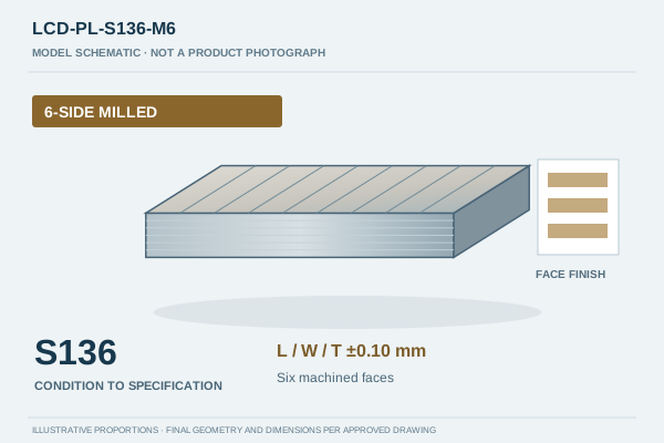
LCD-PL-S136-M6 face-finish schematic; illustrative geometry, dimensions per drawing
Original model schematic · illustrative geometry
LCD-PL-S136-M6

S136 Six-Side Precision Milled Plates

S136 Precision Tool Steel Plates · product details →

All six faces precision milled to the agreed finished dimensions. Use the drawing to identify any additional grinding requirements.

Six precision-milled faces

Length / width
±0.10 mm
Thickness
±0.10 mm
Buyer questions for this model →Finishing specifications & grade options →
View model specifications & supply scope
Material condition
Finish dimensions and material condition are agreed for the selected grade. Large plates and additional geometric requirements need drawing-specific review.
Size capacity
Regular: 100×100×20 to 800×600×300 mm. Maximum processing: 1200×800×400 mm, subject to grade, condition and finish review. The maximum is not an E1 tolerance envelope.
Parallelism
0.08 mm / 100 mm. Confirm any whole-span acceptance and additional geometric requirements on the drawing.
Reports
MTC, hardness and dimensional reports available. UT reports by request with an agreed scope.
Typical production
3–7 working days after the order-start conditions are completed. Transport time is separate.
Full technical scope →
Inquire about this model →
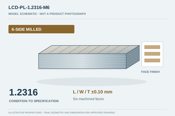
LCD-PL-1.2316-M6 face-finish schematic; illustrative geometry, dimensions per drawing
Original model schematic · illustrative geometry
LCD-PL-1.2316-M6

1.2316 Six-Side Precision Milled Plates

1.2316 Precision Tool Steel Plates · product details →

All six faces precision milled to the agreed finished dimensions. Use the drawing to identify any additional grinding requirements.

Six precision-milled faces

Length / width
±0.10 mm
Thickness
±0.10 mm
Buyer questions for this model →Finishing specifications & grade options →
View model specifications & supply scope
Material condition
Finish dimensions and material condition are agreed for the selected grade. Large plates and additional geometric requirements need drawing-specific review.
Size capacity
Regular: 100×100×20 to 800×600×300 mm. Maximum processing: 1200×800×400 mm, subject to grade, condition and finish review. The maximum is not an E1 tolerance envelope.
Parallelism
0.08 mm / 100 mm. Confirm any whole-span acceptance and additional geometric requirements on the drawing.
Reports
MTC, hardness and dimensional reports available. UT reports by request with an agreed scope.
Typical production
3–7 working days after the order-start conditions are completed. Transport time is separate.
Full technical scope →
Inquire about this model →
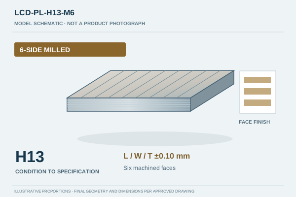
LCD-PL-H13-M6 face-finish schematic; illustrative geometry, dimensions per drawing
Original model schematic · illustrative geometry
LCD-PL-H13-M6

H13 Six-Side Precision Milled Plates

H13 Precision Tool Steel Plates · product details →

All six faces precision milled to the agreed finished dimensions. Use the drawing to identify any additional grinding requirements.

Six precision-milled faces

Length / width
±0.10 mm
Thickness
±0.10 mm
Buyer questions for this model →Finishing specifications & grade options →
View model specifications & supply scope
Material condition
Finish dimensions and material condition are agreed for the selected grade. Large plates and additional geometric requirements need drawing-specific review.
Size capacity
Regular: 100×100×20 to 800×600×300 mm. Maximum processing: 1200×800×400 mm, subject to grade, condition and finish review. The maximum is not an E1 tolerance envelope.
Parallelism
0.08 mm / 100 mm. Confirm any whole-span acceptance and additional geometric requirements on the drawing.
Reports
MTC, hardness and dimensional reports available. UT reports by request with an agreed scope.
Typical production
3–7 working days after the order-start conditions are completed. Transport time is separate.
Full technical scope →
Inquire about this model →
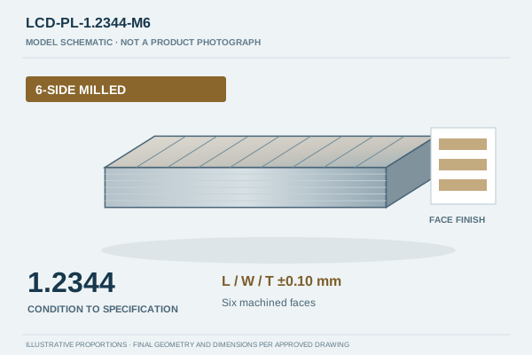
LCD-PL-1.2344-M6 face-finish schematic; illustrative geometry, dimensions per drawing
Original model schematic · illustrative geometry
LCD-PL-1.2344-M6

1.2344 Six-Side Precision Milled Plates

1.2344 Precision Tool Steel Plates · product details →

All six faces precision milled to the agreed finished dimensions. Use the drawing to identify any additional grinding requirements.

Six precision-milled faces

Length / width
±0.10 mm
Thickness
±0.10 mm
Buyer questions for this model →Finishing specifications & grade options →
View model specifications & supply scope
Material condition
Finish dimensions and material condition are agreed for the selected grade. Large plates and additional geometric requirements need drawing-specific review.
Size capacity
Regular: 100×100×20 to 800×600×300 mm. Maximum processing: 1200×800×400 mm, subject to grade, condition and finish review. The maximum is not an E1 tolerance envelope.
Parallelism
0.08 mm / 100 mm. Confirm any whole-span acceptance and additional geometric requirements on the drawing.
Reports
MTC, hardness and dimensional reports available. UT reports by request with an agreed scope.
Typical production
3–7 working days after the order-start conditions are completed. Transport time is separate.
Full technical scope →
Inquire about this model →
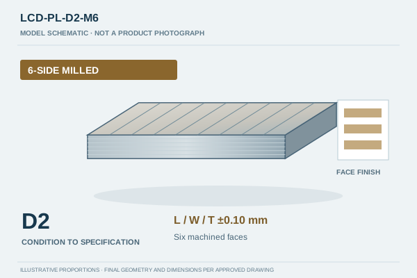
LCD-PL-D2-M6 face-finish schematic; illustrative geometry, dimensions per drawing
Original model schematic · illustrative geometry
LCD-PL-D2-M6

D2 Six-Side Precision Milled Plates

D2 Precision Tool Steel Plates · product details →

All six faces precision milled to the agreed finished dimensions. Use the drawing to identify any additional grinding requirements.

Six precision-milled faces

Length / width
±0.10 mm
Thickness
±0.10 mm
Buyer questions for this model →Finishing specifications & grade options →
View model specifications & supply scope
Material condition
Finish dimensions and material condition are agreed for the selected grade. Large plates and additional geometric requirements need drawing-specific review.
Size capacity
Regular: 100×100×20 to 800×600×300 mm. Maximum processing: 1200×800×400 mm, subject to grade, condition and finish review. The maximum is not an E1 tolerance envelope.
Parallelism
0.08 mm / 100 mm. Confirm any whole-span acceptance and additional geometric requirements on the drawing.
Reports
MTC, hardness and dimensional reports available. UT reports by request with an agreed scope.
Typical production
3–7 working days after the order-start conditions are completed. Transport time is separate.
Full technical scope →
Inquire about this model →
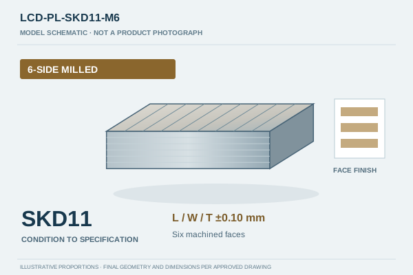
LCD-PL-SKD11-M6 face-finish schematic; illustrative geometry, dimensions per drawing
Original model schematic · illustrative geometry
LCD-PL-SKD11-M6

SKD11 Six-Side Precision Milled Plates

SKD11 Precision Tool Steel Plates · product details →

All six faces precision milled to the agreed finished dimensions. Use the drawing to identify any additional grinding requirements.

Six precision-milled faces

Length / width
±0.10 mm
Thickness
±0.10 mm
Buyer questions for this model →Finishing specifications & grade options →
View model specifications & supply scope
Material condition
Finish dimensions and material condition are agreed for the selected grade. Large plates and additional geometric requirements need drawing-specific review.
Size capacity
Regular: 100×100×20 to 800×600×300 mm. Maximum processing: 1200×800×400 mm, subject to grade, condition and finish review. The maximum is not an E1 tolerance envelope.
Parallelism
0.08 mm / 100 mm. Confirm any whole-span acceptance and additional geometric requirements on the drawing.
Reports
MTC, hardness and dimensional reports available. UT reports by request with an agreed scope.
Typical production
3–7 working days after the order-start conditions are completed. Transport time is separate.
Full technical scope →
Inquire about this model →
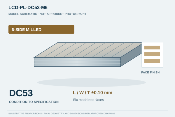
LCD-PL-DC53-M6 face-finish schematic; illustrative geometry, dimensions per drawing
Original model schematic · illustrative geometry
LCD-PL-DC53-M6

DC53 Six-Side Precision Milled Plates

DC53 Precision Tool Steel Plates · product details →

All six faces precision milled to the agreed finished dimensions. Use the drawing to identify any additional grinding requirements.

Six precision-milled faces

Length / width
±0.10 mm
Thickness
±0.10 mm
Buyer questions for this model →Finishing specifications & grade options →
View model specifications & supply scope
Material condition
Finish dimensions and material condition are agreed for the selected grade. Large plates and additional geometric requirements need drawing-specific review.
Size capacity
Regular: 100×100×20 to 800×600×300 mm. Maximum processing: 1200×800×400 mm, subject to grade, condition and finish review. The maximum is not an E1 tolerance envelope.
Parallelism
0.08 mm / 100 mm. Confirm any whole-span acceptance and additional geometric requirements on the drawing.
Reports
MTC, hardness and dimensional reports available. UT reports by request with an agreed scope.
Typical production
3–7 working days after the order-start conditions are completed. Transport time is separate.
Full technical scope →
Inquire about this model →
How to use these model references

LCD-PL identifies a precision plate: G2 = two-side ground / four-side milled; E1 = eligible six-side precision ground; M6 = six-side precision milled. LCD-MB identifies a custom mold base: M = machining scope; A = machining with agreed guide pillar/bushing assembly.

These are Lichengda catalog references for grade/finish or manufacturing-scope options. They do not define an industry standard, fixed dimensions, stock availability or a complete mold. All dimensions, material conditions, components and acceptance requirements are agreed for the drawing.

E1 applies only to its specified grades and conditions, with length and width each ≤600 mm and thickness 10–200 mm. Each steel designation is listed separately; no grade equivalence is implied.

Working days exclude weekends and statutory public holidays in China. Production starts on the next working day after formal PO receipt, final drawing/specification approval and applicable deposit receipt have all been completed.

Each model has an original technical schematic illustrating its finish or configuration scope. Proportions and feature positions are conceptual, not a fabrication design or a statement of supplied hardware. Material grade cannot be verified by appearance. Dimensions, actual layout and acceptance remain drawing-specific.
Start with your drawing.

Tell us the material, finish and requirements for your next project.

Prepare an inquiry